Please note that this is just a overview and no details are handled. If you want further information, please contact me.
Index
Leading In the PSoC Weblab
This project is about the development and realization of a system which allows internet users to develop and test PSoC1 microcontroller software without the need of the user to have any other hardware than any kind of a web-enabled device with a modern web-browser. It is meant for different kinds of users, users who are just interested in a first touch with PSoC1 software development but also for students who need to test more complex software.
This project was my Bachelor Thesis for the exam of Bachelor of Engineeringat the bachelor degree course electrical engineering and information technology. Area of specialization: Energy and Automation Technologies at FH Frankfurt – University of Applied Sciences
The main users of this System are FH-Frankfurt – University of Applied Sciences and Metropolia – University of Applied sciences and their students. Metropolia is using PSoC1 microcontrollers from Cypress for lessons in microcontroller software development and also FH-Frankfurt – University of Applied Sciences is using PSoC1 for lessons but only during an intensive course which is taking place once a year.
Since there is no emulator for PSoC1, a user always needs at least a Windows PC, a compatible Programmer and a PSoC1, this system is meant to get rid of these concrete requirements and to reach a bigger audience. Also emulators cannot be used as flexible as real hardware and normally cannot copy a real device behavior reliable.
Requirements
Accessibility
The System must be accessible from the Internet, through a website, with a modern Browser without the need to have any additional plugins installed.
Programming
The system must be able to interface the PSoC1 to be able to copy the user’s software to the chip. It also must be able to control the way this is done.
Binary file upload
There must be the ability to copy a .hex file to a PSoC, so users can create their very own projects with “PSoC Designer” and then upload the .hex file to the system. This scenario is meant for users who have advanced knowledge with PSoC1.
I/O interaction
As it would not make much sense to work with PSoC1 but having no way to interact with it, there is the need to have any kind of Input Output (I/O) interaction with the PSoC. This gives the user the capability to interact with the uploaded software.
Video connection
Besides the I/O interaction there need to be the possibility to get real-time pictures of the PSoC and the periphery of the PSoC. There are components such as a LCD, which cannot be measured directly. By sending real-time images of the component, the user can see what is happening. This is an easy way to let the user now if the uploaded software works as planned. Also this is giving the user the feeling he is dealing with real hardware.
Session Management
Since the system is reachable through the internet, there need to be a session management system which is controlling the connections between the PSoC1 and the users. In detail this means that there is an allowed working time foreach PSoC1, if another user wants to use the same PSoC1, the system must be able to allocate working time fairly.
Additional Requirements
Online compiler
To generate a PSoC1 binary file, “PSoC Designer” is needed. To reach users who do not want or can (e.g. OS-X/Linux users) install this software. There should be the possibility to write software online. This requires any kind of input formfor the user to write the source code and the ability of the system to make a .hex file outof it. However, this will not provide all the features of “PSoC Designer” and is just meant for predefined tasks or first touch experiences.
Serial Interface
To develop PSoC software with a serial interface, there should be the possibility of sending and receiving data from and to the PSoC.
Not Required
Development of laboratory exercises
The system is just a framework.
This thesis is just about providing the possibility of interfacing the hardware through the internet, how this possibility is used is not part of this thesis.
Complete Webpage Design
As the System is just a framework the very final webpage design is not part of the thesis. This includes all manuals and all the texts on the webpage.
Basic information
Microcontroller
In our modern world Microcontrollers are getting more and more important. Almost every electronic device is containing at least one microcontroller. They are responsible for the processing of data, control of periphery and many other tasks. They allow the manufacture to build less complex printed circuit boards (PCB) and, if there is the corresponding interface, the update of devices without the need to change physical components.
A Microcontroller (MCU) is a single chip with build in Microprocessor (CPU), Memory and I/O Devices. It also contains one or more of the following components.
- Analog to Digital converters
- Digital to Analog converters
- Counters
- Clock
PSoC Microcontrollers
During this Project PSoC microcontrollers are used. PSoC stand for “Programmable System on Chip” and is the name for 4 different families of ICs made by Cypress Semiconductors, California, USA.
PSoC families (Source : cypress.com/psoc/ 24.06.2013)
- PSoC1 8-bit M8C
- PSoC3 8-bit 8051
- PSoC4 32-bit Cortex M0
- PSoC5 32-bit Cortex M3
The benefit of those Microcontrollers is that they include mixed-signal arrays of integrated analog and digital peripherals which can be configured also dynamically. To learn more about that, please visit: http://www.embeddedinsights.com/epd/cypress/cypress-psoc.php
Those peripherals are separated from the core but can be accessed from it.
PSoC1
The System is developed for PSoC1. The reason therefore is that PSoC1 is already used at FH-Frankfurt and Metropolia which are the main users. Another reason is that PSoC1 firmware development is nearer to the hardware than the development of PSoC3/4/5 and is providing a better learning effect regarding basic microcontroller skills.
Hardware Specifications for PSoC1 (237 versions, Source : cypress.com/?id=1573 24.06.2013)
- Clock Up to 24 MHz
- Flash 4 KB to 32 KB
- SRAM 256 bytes to 2KB
- Voltage 1.7 V to 5.25 V
- Up to 64 I/O Pins
- Up to 16 programmable digital blocks (for counters, PWM etc.)
- ADC*
- DAC*
- Serial Communication* USB, I²C, SPI, UART
*not all versions
PSoC1 Firmware Development
The Software used for PSoC1 Development is called “PSoC Designer” which can be downloaded for free from cypress.com for Windows Systems. It is an integrated development environment (IDE) which allows configuring all the settingsof the microcontroller and also writing the program code in C or Assembler. It also contains a build in programming software which can be used to write the firmware to the microcontroller using a programmer. When compiling a project, a .hex binary file is generated which represents the program code and settings. The .hex file then can be copied to a microcontroller.
PSoC Programming software
Besides the “PSoC Designer” there is “PSoC Programmer” which is standalone software that is able to copy .hex files to a microcontroller (programming). It also can be downloaded from cypress.com.
PSoC Circuit (Evaluation Board)
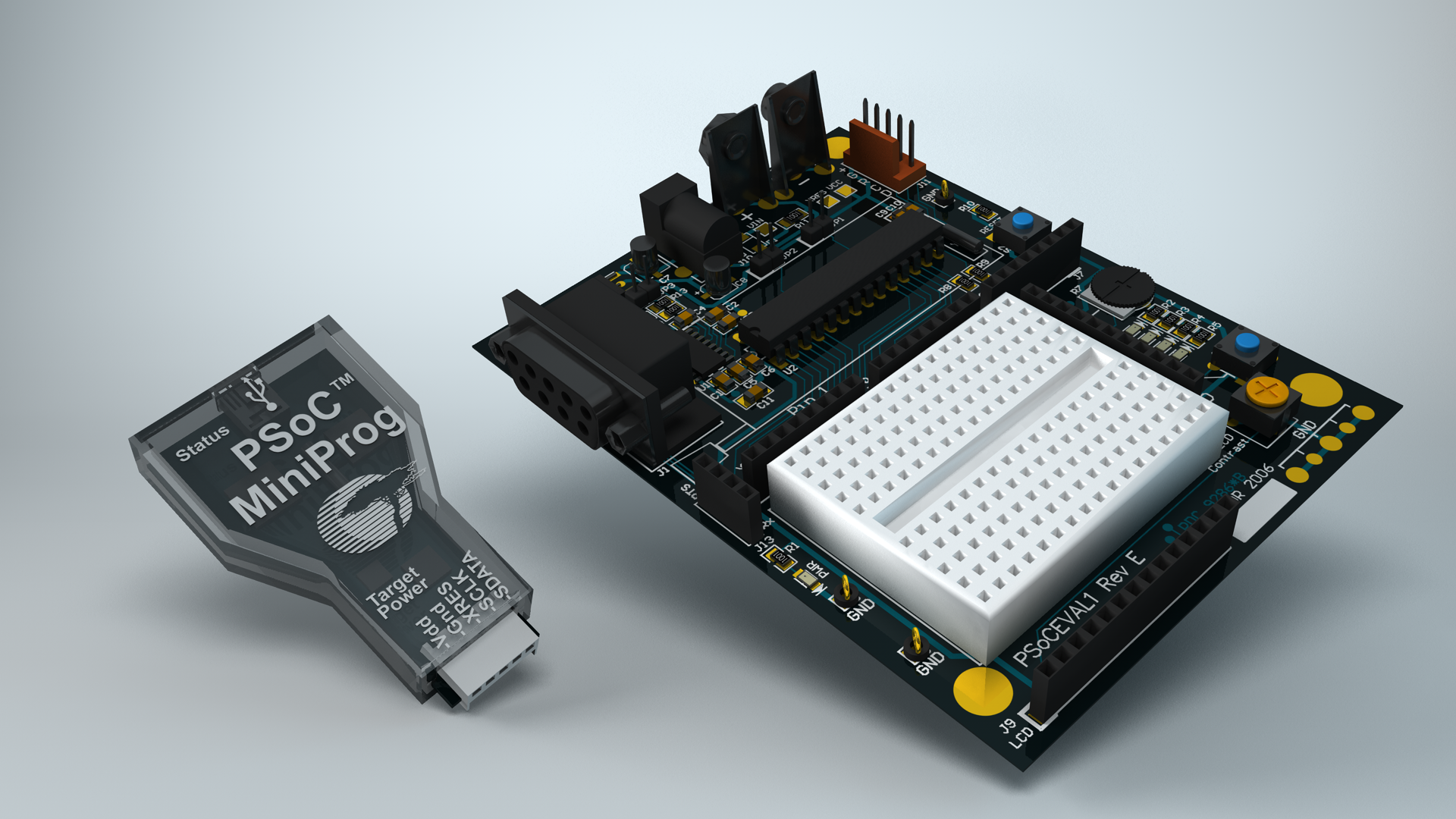
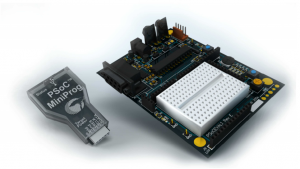
There is no sense just programming a PSoC when it is not attached to something else. At the Universities, students normally use so called “Evaluation Boards”. These are PCBs with a peripherals like a Breadboard, Voltage Regulators, LEDs, LCD, etc. This is giving the chance to let the PSoC interact with other Components. The most common Evaluation Board is the “PSoCEval1” from Cypress. Below there is a image of the PSoCEval1 main components such as the development board and the programmer.
PSoC1 Programming Protocol
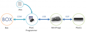
For copying the .hex file to a device, a programmer is needed. The system is designed for the use with PSoC MiniProg1 which is an ISSP programmer connected via USB. The protocol for programming the PSoC1 is ISSP (in-system serial programmingprotocol). It is a proprietary protocol used by Cypress.
The advantage of ISSP is that the microcontroller can be programmed in a circuit which means that the microcontroller can remain in an existing circuit while programming. Also the Pins used for programming can be used otherwise when the programming procedure has finished.
To learn more about .hex files and ISSP please see “PSoC® 1 ISSP Programming Specifications” (Document #: 001-13617) which can be found at cypress.com/?docID=35790 .
PSoC1 Programming mode
There are two modes for programming with ISSP which are Reset and Power Cycle. When starting up, PSoC1 is waiting for programming instructions. It is possible to restart the device by pulling the Reset pin to high (provided by MiniProg1) and after pulling it to low immediately begin the programming procedure. This should be the preferred mode.
However, some PSoC1 do not have a reset pin, if the circuit is powered by the MiniProg1, Power Cycle can be used to repower the PSoC and reset the microcontroller.
Concept
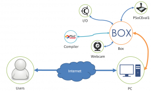
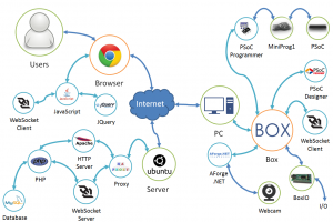
The basic idea is that there is a PC hosting an application that is able to interact with the peripherals and is able to make those peripherals accessible remotely. This application had been named “Box”. Box is able to establish a connection to the PSoC but is also able to interact with any kind of I/O device. It is able to communicate with the compiler, can get images from a webcam and has some kind of internet interface to transfer the information to the user. If you want to learn more about the systems structure, please visit http://psoc-weblab.de/?show=about#structure where you can find an interactive overview.
Interfacing MiniProg1
To Interface the MiniProg1 “PSoC Programmer” is needed. Also the USB-Drivers for MiniProg1 need to be installed. “PSoC Programmer” is providing 2 different methods of accessing the Hardware.
Command Line Interface
“PSoC Programmer” can be used by writing commands to the Command Line using its Command Line Interface (CLI). This is giving the possibility to access the Programmer functions, not only from MiniProg1 but also from all other Cypress Programmers.
A full documentation can be found in the “Command-Line Interface (CLI) Guide, Doc. # 001-16300“ which can be found at the installation directory of “PSoC Programmer”.
This is a good method for simple applications e.g. when developing a system which is copying the same .hex with the same parameters all the time. Then even a simple .bat script is enough to make it work. Since it does not provide any eventsand this project should use all the features of the programmer the CLI is not an Option.
Component Object Model (COM) Interface
A more advanced method is the Component Object Model (COM) Interface (do not confuse with serial port). COM is a binary-interface standard which was introduced by Microsoft in 1993. It enables interprocess communication and dynamic object creation between software components. This means that the Programmer can be used as an object within the Application, providing all the Programmer features.
A full documentation can be found in the “Component Object Model (COM) Interface Guide, Doc. # 001-4520“ which can be found at the installation directory of “PSoC Programmer”.
I/O Interaction
To realize the I/O interaction there was the offer from the adviser to use another PSoC Device. This PSoC is providing a USB interface and supports USB-UART, USB-UART is emulating a serial Port which then can be used to send and receive serial data. This means that this PSoC can easily be used to measure and switchI/O signals. In what follows this system is called “BoxIO”. A PSoC Firmware based on this device (CY7C64215-28PVXC) is needed which is able to switch Pins and measure the state. Within Box there is a system interfacing with the device interpreting the messages received and able to send messages.
For sending information a protocol is defined.

How to use the compiler
.hex Compiler
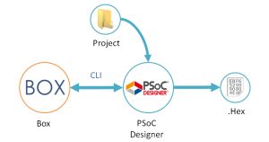
“PSoC Designer” has got a Command Line Interface (CLI) which is called PDCLI. With this interface it is possible to compile “PSoC Designer” Projects to .hex files. This will enable web users to create .hex files without having “PSoC Designer” installed. This component requires having a list of all “PSoC Designer” installations of the system. It is getting this list from the systems registry. It then needs to search for the PDCLI. The module allows selecting a “PSoC Designer” Project and then compiles a .hex file.
Projectmaker
The Projectmaker is meant for web users who have not installed “PSoC Designer” on their computer. The idea is to have predefined “PSoC Designer” Projects where all the hardware and module settings are made.The user then can work within those projects (main.c file) and compile the Project using the .hex Compiler. The Projects, which are called templates, are compressed to a.zip file and stored at a defined template directory. If a template was selected, Box extracts it to a temporary template folder and sends the main.c file to the user. If the user is done working with the main.c file, it can be saved to the temporary template folder. After that, the .hex compiler can be used to generate a .hex file which then can be programmed to the PSoC. The advantage is that every time a user selects a template, it is extracted from the .zip and therefore is always in the same condition.
Getting pictures of the Circuit
The easiest way to get a picture stream to a computer is a webcam. There are many ways on how to get the webcam stream into Box. But when comparing, AForge.Net seems to be the simplest when developing with .Net. AForge.Net is a Framework which is originally meant “for developers and researchers in the fields of Computer Vision and Artificial
Intelligence – image processing, neural networks, genetic algorithms, fuzzy logic,
machine learning, robotics, etc.”
There is the possibility to select the connected webcam and to change the settings. A preview within box is needed to adjust the webcam position. The system is sending single JPEG frames to the web user. If the script had received a frame it will request a new one.

Establishing a data connection between the peers
Technology
Different solutions such as polling, webRTC and WebSockets had been discussed. As this system needs very low latencies polling was not an option, webRTC has no free .Net implementation yet (spring 2013) so WebSocket was the choice. I made a small demo page with animations to show how WebSockets work and what are the differences, here (please note that the page still is in an early state)
Format
All Software within this project is object oriented, therefore I chose JSON as a data format between the peers. It would be possible to design an own protocol but this would take too much time and it would not be sure if it is reliable. As mentioned, WebSocket is used for the transport. WebSocket is mainly message based, therefore it basically transport string messages. All the raw data must be contained in a string format. JavaScript Object Notation (JSON) is a compact data format used to serialize objects into a string. It is used in this project for the communication between the browser and Box. The advantage is that it allows to easily send data instead of having an own protocol defined. It also makes sure the containing information is transported unchanged. However, JSON is only transporting the properties. To make an object out of a string again the JSON parser need to know the structure of the object and then is creating a new instance with the given properties. JSON is also able to handle complex data types such as arrays.
Server
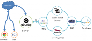
The server is responsible for handling the HTTP request of the web user and also Tunneling the Raw Data from Box to the user Browser. For Session Management a Database is needed. The User and also Box may be behind strong firewalls. Typically the firewalls allow TCP traffic on Port 80. Thats why a Proxy Server is used to split the HTTP from the WebSocket messages. The nice thing about WebSocket is that it is basically a HTTP frame with some modifications. As the webpage contains dynamic content such as the online box instances or the glossary PHP is used to make the HTML dynamic. Also the WebSocket Server is based on PHP.
User Side
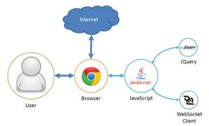
The user side is just a web application. When the user has requested a ticket to work with an instance of box the web application (JavaScript) is loaded and tries to establish a webSocket connection to the Server/Box. Once the connection had been established JavaScript (partial with the help of JQuery) is changing the appearance of the webpage without the need to reload.
Overview
All the components of the system are centralized below
And this is how it looks like when it is in use.
On the first row you get an description of the device you work with. The second row allows to interact with the IO device. You see a stream of the webcam and can communicate with the programmer. As you can see in the video you can write your source code online which is then compiled and copied to the device. It also works on mobile devices.
